Thursday 30 March 2017

1/6 Dragon Sherman Tank build - Part 5 (c): Final suspension assembly

So yesterday the weather was nice enough I was able to get the lower hull outside to prime and paint.
I didn't take a lot of pictures but one tip about painting, if you are using spray paint, try and make your first 2 coats as light as possible.  Do not try and cover the whole model, just give it a light mist.  This allows the paint to stick against the model really well.  I have noticed that since I started doing this the paint adheres much stronger, and doesn't chip or scratch off as easily.

Here is the completed lower hull with paint.  I just use Krylon paint.  Red oxide primer first, in total about 4 coats with the first two just misting. I taped off the area where the suspension attaches first to allow for the glue to attach better.  This will get touched up after the suspension is attached.


Here is the first set of suspension attached.  The stock section kind of snaps into place, mine made a click sound when I put them on.  I then drilled 4 holes where the bottom section sits, and using #5 bolts attached the suspension.  The stock set up uses a small screw from the inside of the hull, not very strong at all.  I perfer the 4 bolt method.  I also used CA glue on the housing for added strength.


Wednesday 29 March 2017

1/6 Dragon Sherman Build- Part 5 (b): Lower Hull completion

In the last post I went though some of the mods to the lower hull to make it more accurate, detailed and complete.  In this segment we finish the lower hull adding all the little things that make the difference between a average model to a museum quality piece.

The biggest area that needs attention in the lower hull is the rear of the hull. Dragon supplies a large plate which is suppose to be a cover and extension.  It really don't have any detail nor does it fit very well, plus it interferes with the exhaust vent.

Instead of using the stock item, I decided to use the rear hull extenders from ECA.  I have used this before on my 1st tank and it worked excellent. This item fits well and is accurate.  It also allows the exhaust vent section to fold up and into it which again is how the real thing works.


Stock plate that is suppose to be a lower hull extension?


Here is the ECA part installed, any gaps filled...


I also created my own rear tow eyes. The stock ones are not very accurate or thick enough. You can have either 4 arms sticking out or two. I choose to use the larger 2 style.


Rear idler mounts attached, I used #5 bolts to hold them in place, just like the real tank.

 Another item some people miss is the little Joe generator, exhaust.  The Dragon supplied piece is ok, but is not hollow and has some casting marks on it. I decided to create my own out of stryene strip. Whether you use the stock one or make your own, make sure you add the little protective cover as its there on the real one.  The cover is there to protect the exhaust from rocks etc thrown up by the wheels/tracks.


You can either have it running straight out or with a little bend in it pointing downward.

And the last thing added prior to primer and paint is the transmission housing bolts which are missing from the model.  There is 10 bolts per side.  I used #6 hex bolts.


Here is the rear section completed with the following additions:
ECA tow hitch extender, Modified Dragon hitch mount;
ECA Rear Idler mounts, real metal bolts #5's;
ECA hull extension kit;
ECA Rear engine Hatch;
Stock exhaust stacks reworked, casting material etc;
Scratch made tow eyes;
Transmission housing bolts (10 per side);
Sponson access caps (1 per side);
Little Joe Exhaust with protective cover ; and
weld lines.

For weld lines, I use milliput and a little metal tool to create the marks. The Sherman has smoother welds then most, so a real pronounced scalp shape is not necessary although looks good when painted. Weld lines run along the inside of the sponsons, and once the upper hull is in place, weld lines will be place on the outer side as well.  Also along the bottom of the rear plate.


Now the lower hull is complete and ready for paint. Due to the size I need to paint outside so right now I need to wait for the weather to get nicer.  I will also add a little weathering to the under side.  Again, its starting to get heavy so better to do this now then try and do it once the tank is built.

Next post....Final suspension assembly.


Monday 27 March 2017

1/6 Dragon Sherman Build - Part #5(a): Lower Hull

So, if you have been following along, we now have a full set of working suspension.

Now that is out of the way, we can turn our attention to the lower hull.  Why the lower hull you ask?  Well, the lower hull is where all the suspension attaches to.  But more importantly, its the next logical step in building this tank.  I like to have the lower half of the tank complete, painted etc before moving to the upper hull and turret.  Kind of like building from the ground up.

The other reason is this thing is going to start getting heavy, and fast.  Once the suspension is on, it is going to be really difficult to flip it over and work on the bottom if you need to.  Better to just do it all before the suspension gets added, that way you can move it around.  These are big heavy tanks once done and the less you have to flip it the better. Its also a good time to get a box or platform for it to sit on where the wheels are off the ground.  Again just for ease of moving it around.

The 1st thing you want to do when working with the lower hull is to remove the excess material cast into the under side of the sponson's.  This material has no purpose and just gets into the way of the front fenders.  Best to remove it while nothing is attached to it.  Its also a good Idea to give the whole assembly a light sanding.  This will remove any flash or off gassing from the plastic and make your paint stick better.


Unknown cast material on lower sponson?


Removed with sandpaper.


Now, I covered the transmission housing in the 1st post of this blog.  It attaches pretty easily to the front of the lower hull with a minimum of fuss.  I wish I could say the same for the rear section.  It has got to be the most frustrating piece on this whole build (next to the tracks, but more on that later).

For one thing it is not wide enough to fit properly and no amount of clamping will make it. Its just to short width wise. Its just made this way from the factory.  So the best you can hope for is to either center it and deal with the little gaps on both sides or align one side and deal with a bit of a larger gap.  I chose to align one side and fill in the gap.  I use home made plastic filler (styrene and paint thinner) as a paste.  It drys hard as plastic because that is what it is. It also helps to tape it in place while the glue is drying that way there is less of a chance of it moving around on you.

But before we mount it, you might want to upgrade some of the parts on it.  The rear hatch is something I changed out on this build. I went with the ECA one as the stock one is way to big, and is just a big mold piece of plastic.  The ECA does require a bit more work but it looks much better, more in scale and it actually opens like the real thing. The other thing I did was fill in the back of the exhaust stacks.  For some reason these are cast hollow.  Filling them in makes them look much better as well as the addition of casting material. Once painted will really complete this area. Brass bolts replaced the stock cast ones.


How it looks out of the box.  The rear hatch is molded in and does not open as well as being to large.
The exhaust flanges have poor bolt detail and will be sanded off and replaced with brass hardware.


In the photos below, I have removed the rear idler wheel sections as I will be replacing them with complete components from ECA, as well as cutting out the stock hatch. If you are using the ECA hatch, you need to add a bit of material around the opening as its a lot smaller then stock. I use styrene material cut to shape and glued into place to fill the gap. As well once the idler sections were removed I needed to add material to this area as well.  ECA sells plugs for this but I wasn't sure if I was going to go this route until I did it....so I made my own parts, although in hindsight I should have just bought the ECA ones.


Rear engine hatch.  Really nice detail and is the correct size


Exhaust stacks hollow in the back?
Filled in with casting resin. Then glued into place and casting material applied.


How it looks semi completed (with out primer and paint of course).


Installation areas to watch out for.


 Due to the poor quality of the rear part, gaps are
left on either side or in my case on one side.  Although I filled in both sides with plastic material as there were tiny areas with gaps.  The bonus of this is it helps create a stronger bond between the rear plate and the hull as well.


Another addition often overlooked is the underneath the sponson.  There are two (one on each side) access caps.  These are ones from ECA.


Next - rear lower hull extensions and adding the Suspension


Thursday 23 March 2017

1/6 Dragon Sherman Tank Build Part 4 Suspension ....

So now you have all your suspension components separated and ready to install, right?  Not so fast.

One of the things to do now, before we go any further, is to build the remainder of the parts. The volute springs, the tension roller the rear tension arm etc.  Another thing to do at this point is to clean up all part lines, sink holes, and other molding issues. Best to do this now cause once this is assembled, its going to be a real pain and maybe even impossible to do this later.

An area I found needing lots of attention is the VVSS volute springs.  Out of the 12, only 3 went together with out modification.  The volute spring is made up of two separate pieces, a large bottom piece and a smaller top piece.  I have no idea why Dragon cast them this way, they could have just made it one piece and solved a number of issues.  The biggest issue is that for some reason, there is some extra material sticking up on the lower part preventing the top from sitting flush.  It is fixed by filing down this material and lining up the two half's.  Then you have the daunting task of getting rid of the part line.  Out of the 12 I think I was able to clean up 1/2 of them....thankfully they are partially hidden.
In this picture you can see the part lines, as well as where the springs sit.  Depending on the diameter of the spring, you may have to drill or file a bit of the material inside these parts.  In my case I just used my dremmel and a sanding disc to open it up.

Once you have all the volute springs together and clean up.  Put them onto the lever.  They just slide on with a little pressure.  put this aside for now.

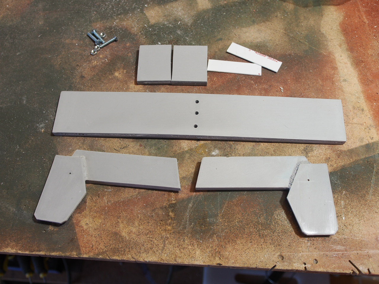
Turning our attention to the next few parts, the rear tension arm and the housing.  The rear tension arm is two large pieces and 4 smaller pieces.  The little pieces are to mimic bolts as well as hold the roller in place.  What is missing is the bolts on the top.  I drill holes and use brass bolts to hold this in place. It also creates a more realistic look as well as allowing me to remove the roller if needed.

Again, clean any part lines at this point while its easy to get access. 

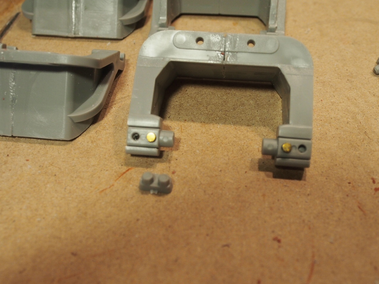
The housing again is 2 parts.  It is the correct shape and size but is lacking foundry numbers, casting material and a number of bolts.  In total there are 16 bolts missing. Thankfully its only 2 different sizes. I use a 3-48 (x8) brass bolt and a #4 - 1/4 (x8). I will explain where they go later in the blog.  

As you can see, I have used yellow milliputt to fill in the lower holes on the rear housing section. This is where the axles will go though and attach. You can do this or add epoxy or JB weld later to secure these bolts.


Once glued together you can clean part lines and add casting material and foundry numbers.  Casting material and numbers go onto the arms as well.  This is where your research goes a long way.  You can use real 1:1 numbers or you can have some fun with it.  I use my kids birth dates, and other fun numbers.  Keep one end of the housing clean, as the roller arm needs to attach there. Keep in mind the arm can go on either end depending one which side of the tank you are working on.  In the end you want 3 arms on the right side and 3 on the left side to coincide with right and left on the tank.

 Roller arm goes towards the rear of the tank. This pic shows a left side housing.

 Casting material and foundry numbers


Now, where do all this missing bolts go? Well there is 8 on each end section (#4's)...and 8 that hold the track tension slider on (#3's).


All holes need to be drilled out first.  If you use the right drill bit the bolts will screw in and help hold the part on.


Front holes can be left open or bolts added. Period photos show both, either open or with bolts.

Another area missing bolts or detail is the lower suspension arms.  There is a small bump where a nut should go, which works at 1/35 scale but not at 1/6th scale. This was fix by running a small brass slot screw into it. Now the top lever would rub on this plate so it would be metal color.


The upper lever is missing details as well. Cast material, foundry numbers and these bolts. Which was correct, with brass bolts.


At this point you can test fit the assembly.  This is how it all fits together with springs in-place.


What it looks like from the underside, spacers used to hold front of arms apart.  Wheel will hold rear arm section apart. I used plastic tube cut at 1" length for the spacer.


Once everything is test and fits properly, its time to prime and paint, especially the vloute springs, lever and lower arms.  There are a lot of small nooks and crannies that is hard to get paint into if you try and paint fully assembled.

Here is what it  looks like all green....but as you can see I forgot a few bolts and needed to add them after painting...


Now there are 3 more parts in the suspension system I have not touched on.  The 1st is the track tension slider, the track tension roller and the wheels.  

The slider is too thick to be accurate.  Depending on your skill level,  You can replace it with a fabricated  brass or metal one, or you can do what I did and just file the stock one down to an acceptable level and call it a day.                                  


Top (green) has been sanded down, bolts (just tops) added to the underside, primed and painted. The flat section will get dry brushed sliver or metal....


You can see the top one is much thinner...if you go this route don't go too thin, you still want it to support the track. Now this part would be painted green at the factory but once it started rolling, the paint would be scraped off showing metal underneath.  I light dry brush of silver works well in this case, but only where the track would touch.


The next part is the tension roller.  Not much to really say here other then glue together, clean the part line and prime and paint.  The sides should be green/camo and the part that touches the track a metal or silver color as the paint would rub off by the tracks. If you added bolts to the tension arm, you can add this last during your build process.  If you are gluing this in, paint it prior to and then tape and paint the rest.


Now the last part is the wheels.  The stock wheels are ok, but like a lot of this model, soft in detail, missing bolt heads, zert fittings and are hollow on the back side.  You could add all these parts and fill in the back,  but it would take you a long time.  I did this on my 1st build. Or you can go the route I am going and add East Coast Armoury's excellent inserts.  If you go this route there is some work to make them fit.  Make sure you sand enough casting material off that the insert fits so that there is a little lip from the stock Dragon wheel.  Once glued in place, I used putty to fill the gap between the insert and the wheel.  This can then be sanded down to a nice smooth transition.  See pic 2. The wheel on the left is glue and putty, wheel on the right is completed, glued, putty, sanded and painted.  The wheel itself is black in color and will be painted later.


Now if you have done everything sort of right your new "correct, articulating" suspension should work kind of like this..(you may have to play we the lever spacing to make it glide correctly).


http://www.eastcoastarmory.com/m4.htm


Parts used:
www.microfasteners.com
plastruct.com
http://www.eastcoastarmory.com/

Next Post....assembly of the trucks/boggies, and paint